Neil Dobie, P.Eng.
Introduction
Floating walkways for purposes of pedestrian, light material and cable conveyance are used extensively in mine tailings ponds in Canada. These structures often consist of a plurality of interconnected floating modules extending over the pond surface. As loading conditions change due to weather conditions and seasonal pond level changes, so the loading changes and the relative positions of the shore access point and the desired service point. In order to accommodate these end point position changes, the walkway assembly requires flexibility to bend when the end points are close together.
The walkway assembly must also be long enough to ensure that it is not pulled tight when the end points are furthest apart. To reduce loads, the walkway assembly is required to assume an arc shape when subject to loading from weather conditions. The flexible design of the walkway assembly must still ensure safe access over water through all weather conditions, specifically handling the snow and ice accumulation in Cold Climates. These situations illuminate the need for a robust connection between modules and between service points (the ends of the floating walkway) while maintaining stability. The existing status quo for floating walkways has resulted in numerous failures of the module connections and has been shown to have a low reserve of stability. The known issues with the current designs are discussed in detail below.
Module to Module Connections
As the modules are often small to allow for ease of transportation, they can tend to move independently of one another under the influence of waves and other environmental loads. Furthermore, modules tend to initially be positioned on land in anticipation of rising pond levels, and thus conform to changing topology. Lastly, as the path between service points change, the modules must pivot about their connections to compensate. The resulting combination means connections must support load, transversely, longitudinally and vertically, while providing limited rotation about the longitudinal axis (twisting), horizontal axis (pivoting), and the transverse axis (pitching), sometimes simultaneously. This movement stands as a barrier to providing smooth, safe, and easy transition between connected modules.
The most common method to allow for relative movement between modules is with pintle hitches for road vehicle. Pintle hitches, while cost effective and readily available, only allow for a limited degree of freedom and are not suitable for a marine environment, resulting in numerous failures.
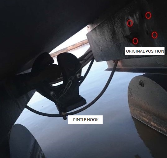
Figure 1: Pintle Hitch Failure
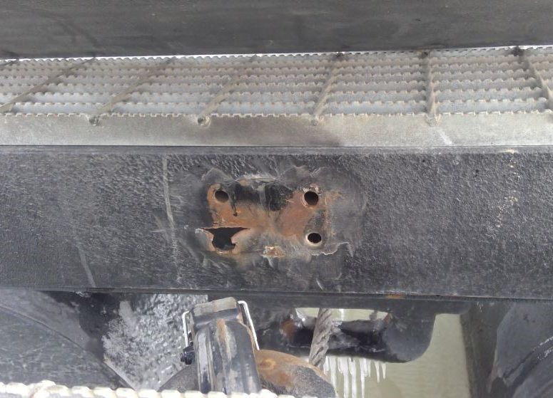
Figure 2: Pintle Hitch Tearout
These failures result in increased maintenance cost, risk to personnel that rely upon the floating walkway for escape egress from the floating asset and potential downtime of the floating asset. Many of the floating walkways carry power and control cables from shore to the floating asset.
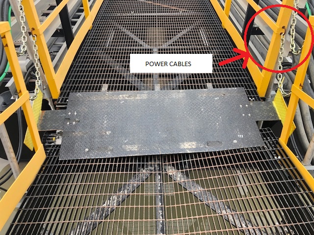
Figure 3: Floating Walkway Photo
When the pintle connections fail, the modules become free to move and could hang on the cables resulting in costly damage. The failures occur because the pintle connection is not designed for the loads experienced. Commonly applied pintle hooks are rated for 10kips or 20kips, while the walkway loads can be upwards of 50kips on large system. Additionally, the structures backing the pintle hooks are designed for even lighter loads resulting in structural failures, as can be seen in Figure 2. The current status quo is to use walkways with a standard pintle without considering the design loads.
In addition to the structural failures, the fatigue and wear requirements of the marine environment are greater than that of road transportation. In a mooring application, the pintles are constantly rubbing against each other, even under light waves. The constant wear has been found to eat the material of the pintle and eye to a point where a significantly lower load than the rated load will result in a failure.
In order to reduce the chance of the pintle connection failing, wire ropes have been used to parallel the floating walkway to be the tension carrying member (Figure 4).
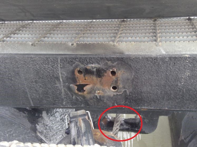
Figure 4: Floating Walkway with Wire Rope
However, the addition of a wire rope has still resulted in failures, as seen in the figure. There are three current theories for this failure:
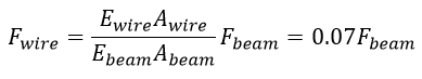
1 – Wire rope stiffness compared to module
The wire rope and the pinned walkways act as a system of parallel springs. As load is introduced to the wire rope, it stretches in accordance with Hooks Law. Wire ropes are constructed to stretch more than steel beams to give them flexibility. This relative change in length needs to be matched by the floating walkways. For long runs of walkways, it is significant. It was calculated that for a 500m length walkway, the relative change in length of the wire rope was 2.0m. As the floating modules are comprised of steel beams, they cannot stretch this much, resulting in the pintle connection being the load carrying member and rendering the wire rope redundant.
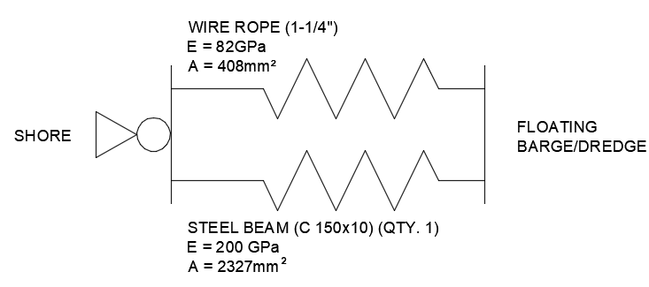
Figure 5: Wire Rope and Structure Spring System
Following Hook’s Law of:
Rearranging, we get:
As the total length of the wire rope and steel beam needs to remain the same, the stretch must also be the same. Therefore:
As the stretch and base lengths are both the same, the split of the forces becomes:
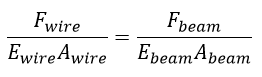
Therefore, the load in the wire rope as a ratio of the steel beam is:
2 -Loads at the water -to-shore interface
Floating walkways often reach land by running up a sloped beach. As water levels rise, more modules begin to float. When a module is half in the water, one end is being supported vertically by the pintle hook and the other by the ground. This results in large vertical loads that the pintle connection is not designed for. This scenario is made worse as the slope of the shore becomes steeper.
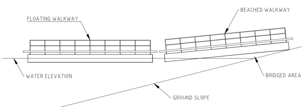
Figure 6: Walkway to Shore Interface
3 – Shock loading imparted by waves
Floating walkways are subject to environmental loads from wind, current and waves. Wave loads are broken down into two categories: first order and second order. First order waves are the peak load and can be thought of when a wave breaks while second order waves are long and slow. First order waves are normally avoided by installing mooring systems that have shock absorption characteristics like catenaries. However, when floating walkway systems are short, they can behave as a rigid connection between the floating asset and shore. In this case, the walkways are similar to a piano wire and the loads on the module connection can increase significantly.
Module to service point connections (termination)
The end of a floating walkway is often connected to a relatively unmoving platform, or shore. To accommodate a large range of motion, it may be required to move more than is practical for the design connection between modules. Unlike the connection between modules, a certain amount of translation in the horizontal plane may also be expected, depending on the module design and attachment method. This can be rationalized by envisioning two fixed platforms connected by a taut straight string. If a load is applied to the string, it must deflect resulting in high loads (piano wire). However, if length can be added to the string, the loads are considerably less. This analogy is akin to the floating walkway where if we uncouple the module and service point, the loading in the floating walkway decreases. A gangway is then required for access between the service point and module.
Floating walkways are often used to provide personnel access as water levels rise. The walkway system will be installed at low water with most of the modules placed on dry land. As the water level rises the number of dry modules will decrease and the number of floating modules will increase. Only the floating modules are able to move to assume the arc shape when subjected to environmental forces (see Figure 7). The grounded modules will remain stationary. This scenario (shown in Figure 7 Catenary Walkway Behaviour) presents an articulation angle problem between the last floating walkway and the first beached walkway.
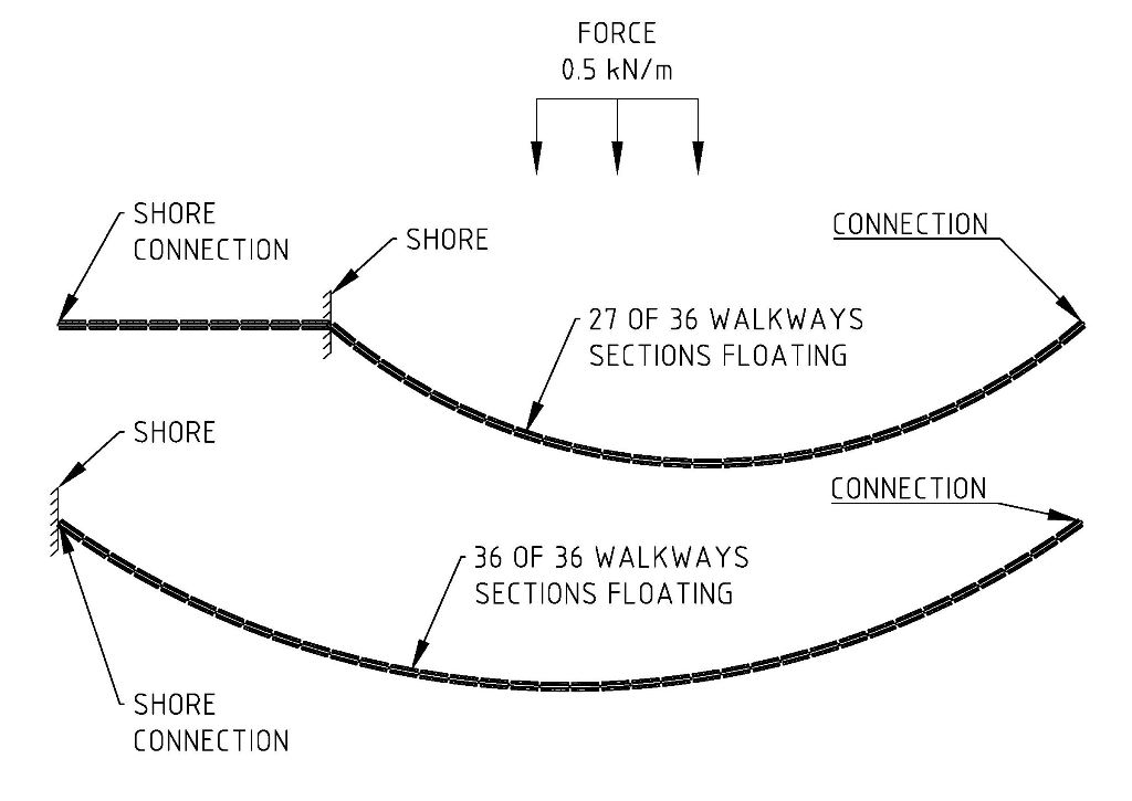
Figure 7: Catenary Walkway Behaviour
To understand the issue CMDL has analyzed the case where three-quarters of a walkway modules in a system of 36 walkways are floating. In this case there will be 27 of 36 walkway modules floating. This leaves nine additional modules on dry ground. The floating modules are modeled as a Catenary curve, as seen in Figure 7 Catenary Walkway Behaviour. The model is examined closely at the interaction of the first floating modules and the first grounded module. It becomes apparent that there will be interference between these two modules shown in Figure 8: Interface between Beached Walkway Section and First Floating Section.
The Catenary parameters (shown in Table 1) are taken from the characteristics of the walkway system.
- Distributed load: w=0.5 kN/m (Maximum wind force given in mooring load calculation) [1];
- Horizontal distance: s=343.73 m (Distance given in mooring load calculation and subtracted by the distance for 9 beached modules) [1];
- Length of curve: L=376 m (Length of 36 Modules. Length of module given in mooring load calculation) [1];
- Vertical Distance: h=0m (Force is defined as perpendicular to walkway to represent worst case)
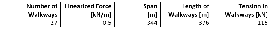
Table 1: Catenary Parameters of the Walkway System with 27 Barges Floating
Figure 8: Interface between Beached Walkway Section and First Floating Section
This interference has the capability to damage the structure of the walkway system, specifically the cable trays, when there is a force that pushes the floating modules from the side.
When a significant number of modules are floating, the force may cause the beached sections to slide to alleviate the interference; however, the force required to move the heavy beached sections across the ground may still be capable of buckling the structure of the walkway system.
Stability
In addition to the need for a robust connection, the primary function of a floating walkway is to float. The current designs are not optimal as the structure is often very heavy compared to the available buoyancy. The stability of a many modular floating walkways when subject to snow and personnel presence is considered by CMDL to be substandard.
Weights
The weight of a floating modules has been estimated based on existing design drawings provided in confidence to CMDL. Many floating walkways from different companies have similar construction but most are approximately 12m (40ft) long and float on two large diameter pipes. The case examined here uses steel OD 914.4mm Pipe with 9.5mm wall thickness (similar to NPS 36 STD pipe).
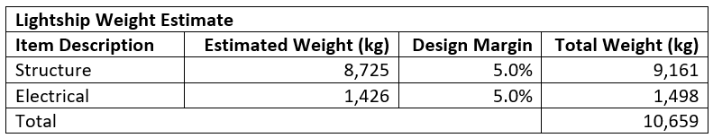
Table 2: Floating walkway weight estimate
Environmental Loads
The single floating walkway horizontal deck area has been subdivided into two areas that have been treated differently:
- Serviced
- Unserviced
The serviced area (1) consists of the walkway grating and the handrails. This area is accessible by site personnel and it is meant to be kept clear of snow/ice with practical frequency.
We have defined ‘practical frequency’ as clearing snow from the walkway no less than once every 5 days. A study has been done to estimate the amount of precipitation occurring in the Fort McMurray area in any given 5-day window when the max daily temperature was below freezing level such that precipitation falls as snow. The maximum amount of precipitation in any 5-day window with temperatures below zero was determined to be 57.6mm which corresponds to 57.6kg/m2 or 0.565kPa.
This value happens to be comparable to the snow load rating dictated by Transport Canada TP7301 STAB7, of 54.0kg/m2 of total deck area. STAB7 ice accretion ratings are meant to be applied to vessels operating in areas where severe ice accretion may be expected but that are also manned and therefore serviced regularly when practical.
This rating has been applied to both the walkway grating and the handrails.
The un-serviced area (2) is the area outboard of the handrails that cannot be accessed regularly and is largely covered by the cable trays. For this area, the Alberta building code for snow accumulation on a roof as well as the site environmental data have been used to calculate the max snow load corresponding to 1.24kPa. The weight of snow results in the following weight estimate for the module.
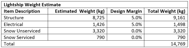
Table 3: Snow Load Estimate on Floating Walkway
The one-minute maximum wind pressure was calculated from the one hour 1/50 year wind pressure provided with the environmental site data; it corresponds to 0.459kPa.
Stability Cases
A series of load cases has been developed and analyzed to represent the most common scenarios. It shall be kept in mind that each walkway module is considered independently from the adjacent modules. No inter-module interactions have been modelled.
1 – Summer – Lightship
The walkway floats with a minimum freeboard of 313mm to the top of the starboard buoyancy pipe. The heel is a result of an imbalance of trailing cables on the starboard side. Pontoon floats typically would not be loaded past 50% to allow for sufficient reserve buoyancy. In the lightest loaded condition, the floating walkways fail the recognized stability criteria in TP 1332.
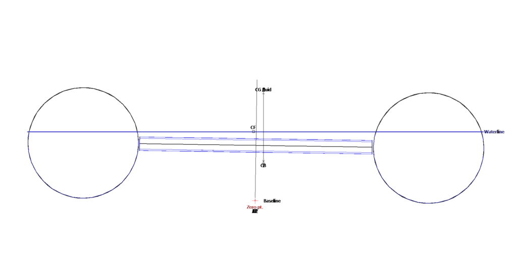
Figure 9: End View of the Floating Walkway in Lightship Scenario
2 – Winter – Snow and Personnel
This case presents the effect of full snow load and two workers standing right on the middle of the walkway. No wind is applied. The walkway floats with 29mm of freeboard to the top of the starboard buoyancy pipe.
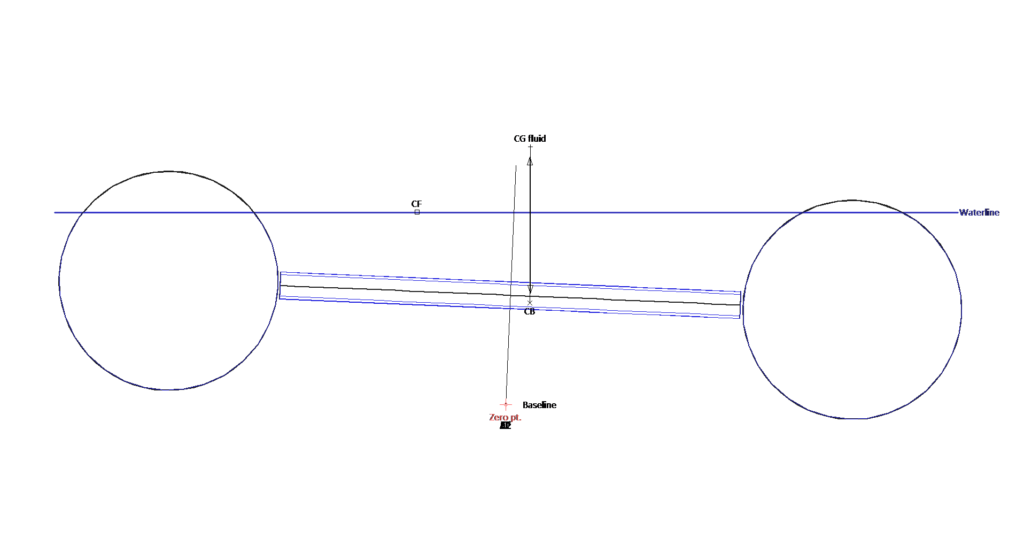
Figure 10: End View of the Floating Walkway in Scenario #2
3 – Winter – Snow Load and Personnel on outboard pontoon
This load case is meant to provide the reader with a practical example to understand the “tenderness” of the walkway when loaded with the full snow load. Two workers are standing on one end of the starboard pontoon. It can be noted that the starboard pontoon is pushed underwater and the waterplane area is disappearing.
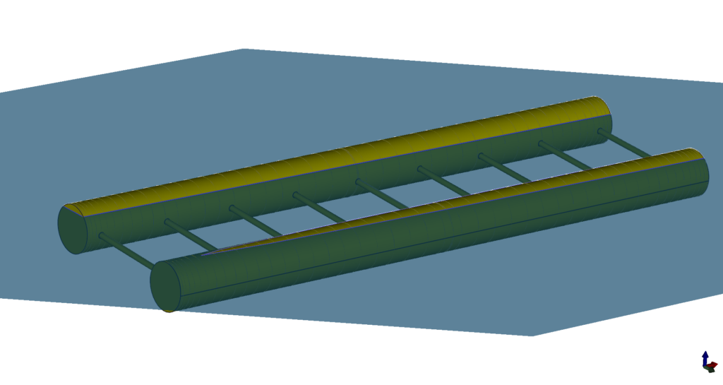
Figure 11: Perspective View of the Floating Walkway in Scenario #3
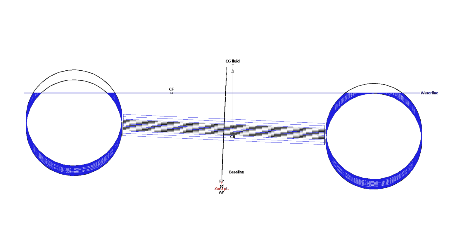
Figure 12: End View of the Floating Walkway in Scenario #3
One additional worker added to the same location will cause the walkway to overturn.
Workers have been used as walkway burden to help conceptualize the tenderness of the walkways; however, burden may arrive due to interaction with waves or additional equipment that is being transported over the floating walkways. It is also possible that snow could collect on one side of the walkway during snow accumulation with wind causing unbalance.
4 – Winter – Snow and Wind Loads
The walkway does not survive wind and snow load applied together. Note on diagram below, the righting arm curve (GZ) never intercepts the wind heeling arm curve. This means that the residual stability of the pontoon is not enough to resist the heeling moment created by the wind. The walkway will capsize.
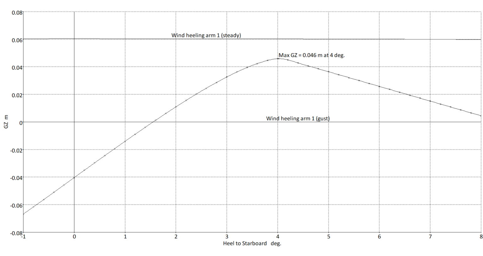
Figure 13: Righting Arm (GZ) Curve for Single Walkway with Snow Loads Applied
Fortunately, CMDL is not aware of any floating walkways capsizing to date. As mentioned previously, the above cases examine a floating walkway as a lone item while in reality, they seldom act alone. By acting as a combined system, rather than individuals, the stability may be enough to have avoided a capsize up to this point.
Next Step
The above concerns with the current state of floating walkways dictates a strong need for an improved design that builds on the current standard design. As we now have a stronger set of requirements for what a floating walkway needs to do, and know of the common failure methods, an improved design can be made. With known design loads, the walkway connections can be made strong enough to withstand the loads and remove the need for a supplemental wire rope. The structure of the walkway can be lightened significantly, greatly improving the stability of the walkways and improving safety.